
Preparation of the surface
A. Remove rust, dirt, grease, oil and other contaminants from the surfaces to be welded.
B. A sound base is required, and this may necessitate removing fatigued or rolled over metal, high ridges or other major surface irregularities. This may be done by gouging (Postalloy®250), grinding or machining.
C. Cracks in the base metal should be arc gouged or ground out and repaired using compatible electrodes. If cracks are through the base metal make sure the end of the crack is removed by drilling or cutting at the end before gouging out the cracks.
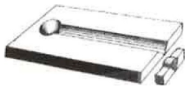
Crack repair using a V groove
D. Previous hardface should be removed if:
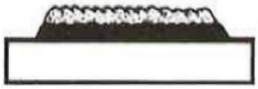
E. If the surface is severely work-hardened, about 1/8” (3mm) of work hardened surface should be removed before hardfacing or build-up of a worn area. Failure to do so might result in weld bead spalling.
Arc gouging removes surface irregularities, work hardened surfaces, or cracks.
F. Edges should be rounded, no sharp edges. This causes excessive mixing of the base metal and hardfacing alloy.
G. if a build-up is needed prior to hardfacing, select a build-up that is compatible with the base metal composition. Never use 7018 as a build-up. Weld Polarity Weld polarity strongly effects the amount of dilution. Reverse polarity results in a first layer deposit that is up to 50% base metal and 50% weld metal. Straight polarity, on the other hand, results in less penetration and more favorable deposit chemistry. A second layer, in either case will produce a chemistry suitable for wear resistance.
Choosing a hardface overlay
A. Never put a soft, ductile weld metal or a work-hardening manganese alloy on top of a harder, more brittle hardfacing alloy. Deposits may spall and come loose. The softer alloy should always be applied beneath the harder deposit. Never use 7018 as a cushion or build-up. It does not have the hardness and strength for hardfacing applications.
B. When two metal parts come in contact with each other, the following guideline is suggested. The part that is easiest to change out or hardface should be about 10 points softer than the part that is more complicated to work on.
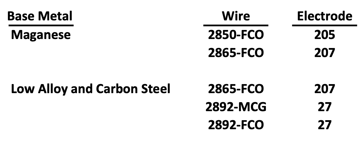
C. Never use a mild or low alloy steel on manganese. The weld deposit will be brittle.
D. If a manganese part is to be repaired repeatedly, such as hammers or railroad frogs and switches, apply one or two layers of Postalloy®2865-FCO (207 electrode) the first time is very beneficial.
E. The more wear resistant the deposit and the higher the alloy content and hardness, the greater will be the tendency to crosscheck. They appear during cooling and are due to the different shrinkage rates between the hard surfacing material and the base material. A regualr check patters is desirable as it will reduce or even eliminate the tendency for distortion. These cracks do not normalloy extend into the base material and do not weaken the bond to the base. Cracks should be transverse across the weld and less than 1” apart. If not, increase the travel speed.
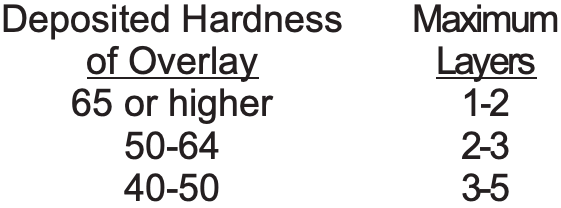
Hardness and number of layers
Limit deposit thickness. Thick hardfacing deposits may crack and break off rapidly in service. Furthermore, as hardface overlays increase in hardness, they tend to be more brittle. Unless an alloy has been specifically designed and tested for multi-layer weld overlays, the following guide lines should be useful to determine the number of hardface layers that should be applied. If it is necessary to apply more layers than is specified for the alloy, a build-up material should be applied first.
Dilution
Consideration must also be given to the dilution that will occur withy the base metal. A weld deposit is a mixture of the filler metal and the base metal, and the deposit chemistry will depend on how much of each is present. Wear resistance is reduced by high base metal dilution. The following suggestions will help minimize dilution, resulting in greater wear resistance.
1. Do not use excessive welding currents.
2. Direct the arc on the molten weld metal rather than on the base metal.
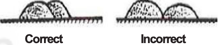
3. Use close overlap (50 to 75%) when placing weld beads side by side.
4. Use DC straight polarity if possible (electrode negative).
5. Do not use excessive preheat. Preheat with recommended ranges.
6. Regardless of stringer or wide weave beads, the travel speed should be adjusted to direct the arc on the weld puddle.
7. When using wire processes, a longer stick-out will reduce penetration.
8. In order of decreasing penetration and dilution - vertical up (highest), horizontal, up hill, flat and down hill (lowest).
Manganese Steel.
Do not preheat manganese. The tough properties of manganese can be lost if the base metal is continually heated above 500°F (260°C). Weld beads should be distributed so as to avoid concentrated and prolonged heat input into one area.
Cast Iron.
Cast iron requires high preheat temperatures for hardfacing applications. A good rule of thumb is dull red.
Carbon and Low Alloys Steels.
Preheating of some carbon and low alloy steels may be necessary to minimize distortion, spalling, underbead cracking and cracking in the base metal. Preheat temperature is influenced by carbon and alloy content, part size and rigidity. The higher the carbon and alloy content, the higher the required preheat temperature. Consult the preheat chart or call Postle Industries for recommendations. The preheat should be uniform throughout the part and the part should be slow cooled.
Hard surfacing alloys are usually much harder and of a much higher alloy content than the base metal. Applying a cushion or buffer layer provides a transition between the softer parent metal and the hard overlay.
The cushion layer has several purposes
1. Most hard surfacing alloys are limited to two or three layers, some only one. Therefore, some applications require that an intermediate layer be used to build up the part close to finish dimensions prior to depositing a harder, more abrasion resistant alloy.
2. When hard materials are used on soft base metals, such as mild steel, there is a tendency for the hardfacing layer to “sink” into the soft base metal under high load conditions. This may result in spalling of the hardfacing alloy. An intermediate buffer layer will help to prevent this from happening.
3. Hard surfacing alloys check-crack throughout the deposit. The buffer layer helps to prevent these cracks from propagating into the parent metal.
4. If the surface conditions involve thermal cycling, large thermal property differences between the parent metal and the overlay can lead to fatigue problems and spalling. The deposition of a buffer layer provides a very effective transition between the weld and the overlay.
5. Never use 7018 as a cushion or build-up. It does not have the hardness and strength for hardfacing applications.
Alloys in this category are used on many different parts and components
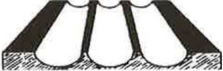
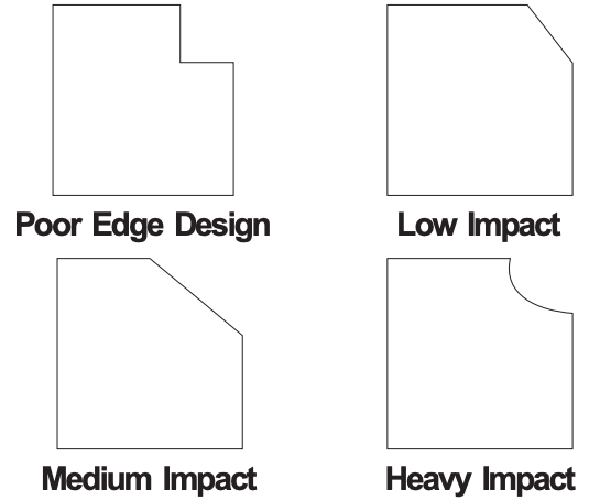
Hardfacing on an Edge
When an edge is subjected to impact or shock, preparation is critical. The following designs are suggested. Sharp corners, where stress cracks can develop, must be avoided.
Selection of the proper hardfacing alloy and preparation of the workpiece are not enough to maximize the service life of a part. The pattern used to make the overlay must also be considered, as it too, will have a bearing on how long the part will last. There are times when putting less hardfacing on a surface is better than covering the entire surface. There are a number of ways that stringer bead patterns are used depending on the service conditions of the component.

Stringer beads parallel to the direction of travel of coarse rocky material
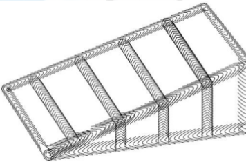
Stringer beads at right angles in the direction of travel of fine sandy material
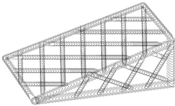
Stringer beads in waffle pattern for mixed conditions or when fine material might easily pack
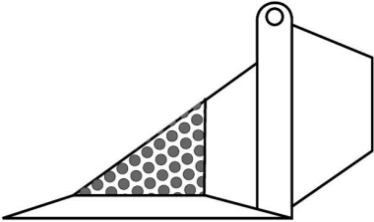
Dot Pattern for less critical areas
Postle Industries • E-mail: sparky@postle.com